The monostable multivibrator is also called as the one-shot multivibrator. The circuit produces a single pulse of specified duration in response to each external trigger signal. For such a circuit, only one stable state exists. When an external trigger is applied, the output changes its state. The new state is called as a quasi-stable state. The circuit remains in this state for a fixed interval of time. After some time it returns back to its original stable state. In fact, an internal trigger signal is generated which drives the circuit back to its original stable state. Usually, the charging and discharging of a capacitor provide this internal trigger signal. The circuit diagram of a typical monostable multivibrator using OpAmp is given below:
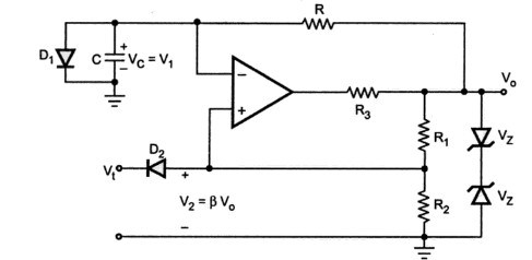
- The diode
connected across the capacitor is called clamping diode. It clamps the capacitor voltage to
when the output is at
.
- A negative triggering pulse is applied to the Non-inverting terminal of Op-Amp through RC differentiator circuit and diode
.
Operation of the Circuit
(i). To understand the operation of the circuit, let us assume that the output 

(ii). The diode 


(iii). The voltage at the non-inverting terminal is controlled by voltage divider circuit of 

Voltage at non-inverting terminal

(iv). If 


(v). The diode is now reverse biased and the capacitor starts charging exponentially to 
(vi). The voltage at the non-inverting terminal is now 

(vii). The capacitor now starts charging towards 


Expression for pulse width 
Initial voltage ( at 

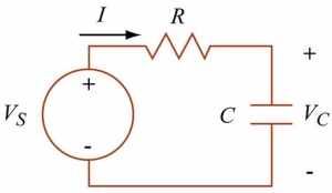
Here Role of supply Voltage will play output voltage

Voltage across Capacitor at time 
![\displaystyle V_{C}(t) = V_{D_{1}} \; e^{- \left(\dfrac{t}{RC} \right)} + V_0 \; \left[1 - e^{- \left( \dfrac {t}{RC} \right)} \right]](https://s0.wp.com/latex.php?latex=%5Cdisplaystyle+V_%7BC%7D%28t%29+%3D+V_%7BD_%7B1%7D%7D+%5C%3B+e%5E%7B-+%5Cleft%28%5Cdfrac%7Bt%7D%7BRC%7D+%5Cright%29%7D+%2B+V_0+%5C%3B+%5Cleft%5B1+-+e%5E%7B-+%5Cleft%28+%5Cdfrac+%7Bt%7D%7BRC%7D+%5Cright%29%7D+%5Cright%5D%C2%A0+&bg=ffffff&fg=222222&s=1&c=20201002)
At time


If 

Then 
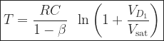
For Monostable operation, the trigger pulse width 

The diode 
It can be seen from the waveform that the voltage 


Wow, this was usefull. Keep writing this kind of posts, you will get a lot of people to this text if you continue writing this. I will be visiting this domain more often. thanks
LikeLiked by 1 person
Thanks for your kind words.
LikeLike
Your my life saviour
LikeLike
Please provide a detailed explanation on the wave form pattern
LikeLike
Normally I don’t read article on blogs, but I wish to say that this write-up very forced me to try and do so! Your writing style has been amazed me. Thanks, very nice article.
LikeLike
Aw, this was a really nice post. In idea I want to put in writing like this additionally – taking time and precise effort to make an excellent article… but what can I say… I procrastinate alot and on no account seem to get one thing done.
LikeLike
I get pleasure from, lead to I discovered just what I was having a look for. You have ended my 4 day lengthy hunt! God Bless you man. Have a great day. Bye
LikeLike
I discovered your blog site on google and test just a few of your early posts. Continue to keep up the superb operate. I just further up your RSS feed to my MSN News Reader. Searching for ahead to studying more from you afterward!…
LikeLike