The rotating magnetic field can be defined as the field or flux having constant amplitude but whose axis is continuously rotating in a plane with a certain speed. So if the arrangement is made to rotate a permanent magnet, then the resulting field is a rotating magnetic field.
In three phase induction motors such a rotating magnetic field is produced by supplying currents to a set of stationary windings, with the help of three phase a.c. supply.
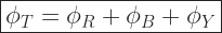
The current carrying windings produce the magnetic field or flux. And due to interaction of three fluxes produced due to three phase supply, resultant flux has a constant magnitude and its axis rotating in space without physically rotating the windings. This type of field is nothing but rotating magnetic field.
Production of Rotating Magnetic Field (RMF)
There are two conditions exist for the production of a Rotating Magnetic field:
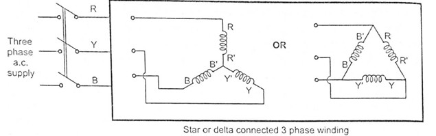
- A three phase induction motor consists of three phase winding as its stationary part called Stator. The three phase stator winding is connected in star or delta. The three phase windings are displaced from each other by
- The windings are supplied by a balanced 3 phase a.c. supply (Means electrically
apart from each other).
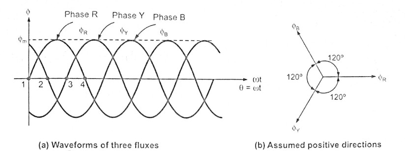
The three phase currents flow simultaneously through the windings and are displaced from each other by 


As windings are identical and supply is balanced, the amplitude of each flux is 


Let 
Case (1): When 


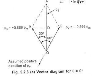
The phasor addition is shown in the figure. 


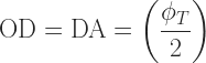
In triangle 

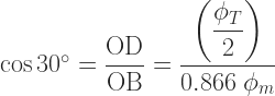

So magnitude of 

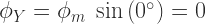
Case (2): When 


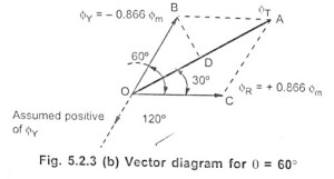
So
Doing the same construction, drawing perpendicular from 


But it can be seen that though its magnitude is 
Case (3): When 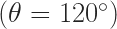


After doing the same construction as before it can be proved again that,
But it can be seen that though its magnitude is
